
In-Service OTDR Fiber Monitoring (RFTS)
Based on OTDR (Optical Time-Domain Reflectometry), this in-service remote fiber test system (RFTS) monitors 100 km of fiber with ±1 m fault location — 24/7 real-time cable health management and sub-second fault localization for telecom and energy networks.
What is In-Service OTDR Fiber Monitoring (RFTS)?
In-Service OTDR Fiber Monitoring — also known as a Remote Fiber Test System (RFTS) — continuously tests fiber optic cables while they remain in service, using OTDR (Optical Time-Domain Reflectometry) as the measurement principle. The system launches test pulses at a wavelength separate from the communication channels and analyzes the backscatter trace, so attenuation events, bending, splices and fiber breaks are detected on live cables without interrupting telecom, power or pipeline communication traffic. Landsub Global's RFTS monitors 100 km of fiber per unit with ±1 m fault location accuracy, turning cable maintenance from ticket-driven troubleshooting into 24/7 condition-based management.
- 100 km monitoring range per unit
- ±1 m fault location accuracy (on-site ±5 m)
- 7×24 online monitoring of live cables
- Non-intrusive testing — test wavelength is separated from communication traffic
- Trend-based degradation alerts — catches gradual attenuation growth before an outage
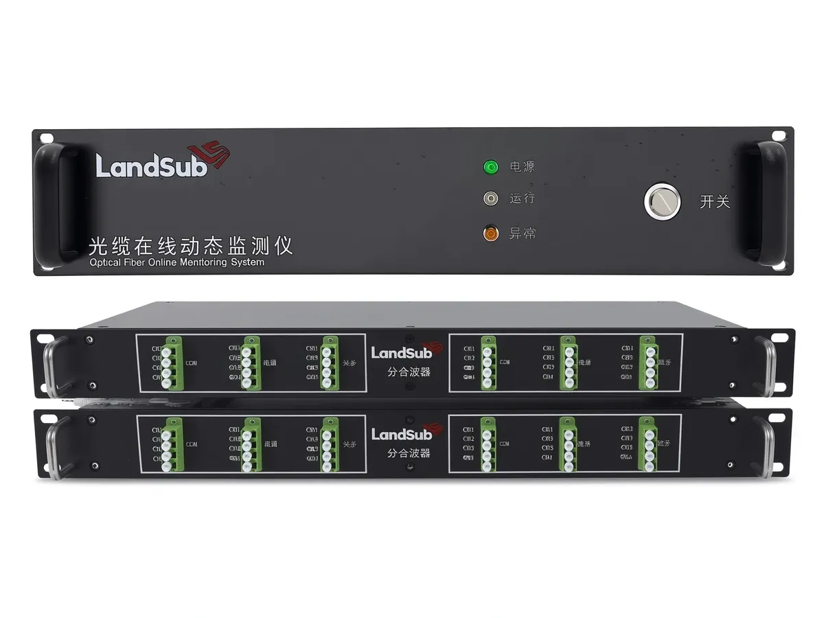
| Specification | Leading OTDR vendors* | Landsub Global |
|---|---|---|
| Monitoring range | 100–145 km | 100 km |
| Fault location accuracy | ±1 m | ±1 m (on-site ±5 m) |
| Monitoring mode | Offline spot testing | 24/7 online monitoring |
*Based on publicly available specifications of leading OTDR test instruments, as of Aug 2026.
Applications: distributed monitoring across telecom, power and pipeline
Telecom operators
Online health management of communication cables.
Transportation
Cable monitoring for rail and highway networks.
Petrochemical
Cable integrity monitoring in plants.
Power
Fiber infrastructure monitoring.
Installation and deployment: how RFTS works
Deployment centers on mapping the operator's real fiber topology, because fault location is only useful when the optical route database is accurate — a distance in the trace must become a distance on the ground.
- Step 1 — Network survey and route documentation. Fiber routes, splice points, splitters and wavelength assignments are documented to build the optical route reference for each monitored cable.
- Step 2 — Baseline trace capture. Reference OTDR traces are recorded for every fiber, so future deviations are measured against the cable's own baseline, not a generic template.
- Step 3 — Unit installation and optical connection. The RFTS unit is installed at the monitoring center and connected to the selected fibers through the test access frame; live traffic is untouched.
- Step 4 — Test scheduling and threshold setting. Automatic test cycles and alarm thresholds — loss, reflection, drift — are configured per cable class and criticality.
- Step 5 — Integration and handover. Fault locations and events are pushed to the operator's NMS or work-order system, and maintenance teams are trained on the localization workflow.
Where RFTS fits: long-distance measurement accuracy, scope and boundaries
RFTS is built for operators who need continuous, objective cable-health data across many route-kilometers — not for occasional spot testing. Every alarm carries a location and a trend, so the response is a work order rather than a hunt.
- Good fit: telecom backbones and access routes, rail and highway communication cables, power utility fiber, petrochemical plant networks, and pipeline communication cables that double as sensing infrastructure.
- Good fit: mixed-vendor cable fleets, because OTDR measurement is fiber-physical and independent of transmission equipment vendor.
- Scope boundary: RFTS reports fiber health and fault location; it does not interpret the carried services, and it does not replace acoustic or temperature sensing of the surrounding asset.
- Not a fit: single short links where a manual OTDR test suffices, and cables with no test access path.
- Rollout pattern: most operators start with their most critical routes, build confidence in the localization workflow, then extend coverage across the rest of the network.
- Route-kilometer economics: the value scales with the network — the more kilometers an operator maintains, the more a ±1 m location matters to repair cost and restoration time.
Conventional offline testing vs continuous online monitoring
The same OTDR measurement serves two very different operating models, and the difference shows up in outage cost:
- Conventional offline testing: a technician brings a portable OTDR to the access point after a fault is reported, tests section by section, and produces a one-off report. Coverage exists only at the moment of the test.
- Continuous online monitoring: a stationary RFTS unit tests the fiber automatically on a schedule, compares every trace against the cable baseline, and raises second-level alarms with ±1 m localization — coverage exists all the time, including before the fault.
- What changes for maintenance: with offline testing the fiber degrades invisibly between tests; with online monitoring, gradual attenuation growth is trended and intervention is scheduled while the cable is still in service.
Frequently asked questions
Detection scope: fault location and degradation on a live cable
Each OTDR test cycle produces a backscatter trace of the whole fiber. The RFTS platform compares every trace against the cable's recorded baseline and classifies the differences, so maintenance teams receive a named event with a location — not a raw trace to interpret.
- Fiber breaks and high-loss events: sudden end-of-trace or step loss changes, located to ±1 m so repair crews dig or open the right closure the first time.
- Gradual degradation: slow attenuation growth from bending stress, water ingress or connector aging is flagged from trend deviation long before service is affected.
- Splice and connector changes: new reflections or loss changes at known splice points distinguish maintenance work from genuine faults.
- Unauthorized route activity: unexpected new events along the route can indicate third-party work near the cable, giving the operator an early call.
Because testing is non-intrusive — the test wavelength is separated from traffic — the same monitored fiber can keep carrying revenue services or pipeline communication while its health is checked around the clock. The result is a shift in maintenance posture: from waiting for outages and locating them afterward, to condition-based intervention while the cable is still healthy.
Further reading
- Optical time-domain reflectometer — the measurement principle behind backscatter traces and fault localization.
- Fiber optic sensor — the broader family of fiber sensing techniques this platform belongs to.
- Distributed acoustic sensing — how the same fiber routes can add acoustic event detection.
Get a configuration and quote
Tell us your scenario — we'll provide a tailored recommendation.
Last updated: September 2026
By the Landsub Global Engineering Team