
Power Cable Fire Detection & Temperature Monitoring (DTS)
±0.5°C accuracy and 0.8 m spatial resolution, turning a single fiber into thousands of temperature sensors for fire early-warning and temperature monitoring of linear assets.
What is Distributed Temperature Sensing (DTS)?
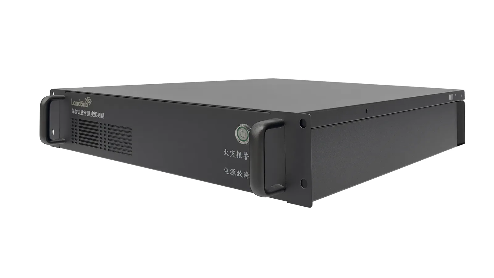
Distributed Temperature Sensing (DTS) is a fiber optic sensing technology that uses Raman backscattering to measure temperature continuously along an optical fiber. A DTS interrogator pulses light into the fiber and analyzes the temperature-dependent Raman backscatter, turning the entire cable into a linear temperature sensor with thousands of measurement points — no discrete probes, no wiring per point, and no field power along the route. Landsub Global's DTS delivers ±0.5 °C temperature accuracy with 0.8 m spatial resolution, so abnormal heating on a power cable, a utility tunnel or a pipeline is detected and localized early, before it develops into a fire or a forced outage.
- ±0.5 °C temperature accuracy (absolute)
- 0.1 °C temperature resolution (relative)
- 0.8 m spatial resolution along the route
- 30 km per channel on single-mode fiber; 20 km per channel on multimode fiber
- 50 °C/min response sensitivity for fast-rising thermal events
| Specification | Leading international vendors* | Landsub Global |
|---|---|---|
| Temperature accuracy | ±1 °C | ±0.5 °C |
| Temperature resolution | 0.01–0.1 °C | 0.1 °C |
| Spatial resolution | 0.65–1 m | 0.8 m |
| Range | 35–70 km | 20 km (MM) / 30 km (SM) |
| Response sensitivity | Not disclosed | 50 °C/min |
*Based on publicly available specifications of leading international DTS vendors, as of Aug 2026. Temperature accuracy (absolute) and resolution (relative) are separate metrics.
Applications: overheating detection from cables to conveyors
Power cable fire warning
Continuous temperature monitoring of power cables to prevent fire incidents.
Cable tunnel monitoring
Distributed temperature profiling across utility tunnels.
Conveyor fire prevention
Temperature corroboration alongside DAS acoustic monitoring.
Pipeline thermal monitoring
Temperature anomaly detection along pipelines.
Installation and deployment: how DTS works
A DTS project is designed around the thermal profile of the protected asset, so configuration starts with the route, not the hardware. The channel plan also determines alarm zoning later, so it is confirmed before any equipment is ordered.
- Step 1 — Route survey and thermal risk assessment. Engineers map the cable route or asset section, identify heat-sensitive zones and confirm fiber availability, type and channel budget.
- Step 2 — Fiber testing and channel planning. Attenuation is measured to verify that each planned channel covers its assigned section within the 30 km (single-mode) or 20 km (multimode) range.
- Step 3 — Interrogator installation. The DTS unit is installed at the monitoring station — typically an existing substation, control room or tunnel entrance — and connected to the sensing fiber.
- Step 4 — Calibration and baseline capture. Reference sections are calibrated, and a normal thermal baseline is recorded so alarms are triggered against measured operating temperature, not generic thresholds.
- Step 5 — Alarm rule configuration and handover. Rate-of-rise and absolute-temperature rules are set per zone, control-room staff are trained, and the system enters continuous operation.
Where DTS fits: long-distance measurement and boundaries
DTS excels where temperature itself is the risk indicator and the asset is long enough that point sensors become impractical. One interrogator, one fiber and one alarm platform cover a route that would otherwise need hundreds of wired probes, each with its own cabling, power and calibration schedule.
- Good fit: underground and tunnel-installed power cables, cable tunnels and utility corridors, conveyor lines needing fire corroboration, pipelines with thermal anomaly risk.
- Good fit: retrofit scenarios where the asset already has a suitable fiber — sensing runs on the existing cable route.
- Combine with DAS: where both heating and third-party intrusion matter (for example power corridors), DTS temperature data complements DAS vibration data on the same route.
- Not a fit: single-device temperature spots (a probe is simpler), environments with no fiber path, and applications outside industrial monitoring scope.
- Validation first: where thermal behavior is unusual — deep burial, shared ducts, high ambient cycling — a short-term trial establishes the baseline before thresholds are fixed.
One operational note: because every scan returns the full temperature curve, DTS also records the asset's normal load cycles. Over weeks of operation this history becomes the reference against which drift and slow-developing hot spots stand out — which is why commissioning a proper baseline (Step 4 above) matters more than any single datasheet number.
Frequently asked questions
How DTS measures temperature — and why accuracy and resolution are separate numbers
DTS measurement is based on Raman backscattering: when a laser pulse travels through the fiber, a small fraction of the light is scattered back with a wavelength shift that depends on the local temperature of the fiber. By timing the returning signal, the interrogator assigns each temperature reading to a position — the 0.8 m spatial resolution — and builds a complete thermal profile of the route on every scan. This is why the datasheet carries two distinct temperature figures: ±0.5 °C is the absolute accuracy of each reading, while 0.1 °C is the relative resolution between adjacent readings, which is what allows small but growing anomalies to be tracked over time.
- Continuous profile, not spot checks: every scan returns the full temperature curve of the route, so drift and hot spots are visible at once.
- Baseline comparison: alarms are evaluated against the asset's recorded normal thermal behavior, reducing nuisance alerts from daily load cycles.
- Rate-of-rise detection: fast temperature increase — the signature of an emerging cable fault or fire — is flagged separately from absolute thresholds.
- Passive sensing line: the fiber carries no electronics along the route, so the sensing line itself is not a fire load in tunnels and cable chambers.
Key terms
- Raman backscattering — the temperature-dependent scatter effect that lets a fiber report temperature at every point.
- Spatial resolution (0.8 m) — how finely the interrogator separates temperature readings along the route.
- Absolute accuracy (±0.5 °C) — how close each reading is to true temperature; specified separately from resolution.
- Rate-of-rise rule — an alarm on temperature gradient, the earliest quantitative signature of an emerging cable fault.
- Channel — one fiber route handled by the DTS interrogator; up to 30 km on single-mode, 20 km on multimode fiber.
Further reading
- Distributed temperature sensing — the Raman-based measurement principle behind DTS temperature profiles.
- Fiber optic sensor — the technology family of distributed and point fiber sensing.
- Distributed acoustic sensing — the companion technology for vibration and intrusion on the same route.
- Optical time-domain reflectometer — how backscatter timing gives position along the fiber.
Get a DTS configuration and quote
Tell us your asset length and accuracy requirements.
Last updated: September 2026
By the Landsub Global Engineering Team